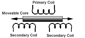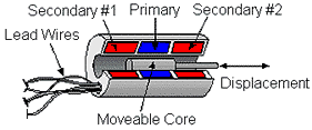


 An LVDT is much like any other transformer in that it consists of a primary coil, secondary coils, and a magnetic core. An alternating current, known as the carrier signal, is produced in the primary coil. The changing current in the primary coil produces a varying magnetic field around the core. This magnetic field induces an alternating (AC) voltage in the secondary coils that are in proximity to the core. As with any transformer, the voltage of the induced signal in the secondary coil is linearly related to the number of coils. The basic transformer relation is:
(1)
As the core is displaced, the number of coils in the secondary coil exposed to the coil changes linearly. Therefore the amplitude of the induced signal varies linearly with displacement.
 The LVDT indicates direction of displacement by having the two secondary coils whose outputs are balanced against one another. The secondary coils in an LVDT are connected in the opposite sense (one clockwise, the other counter clockwise). Thus when the same varying magnetic field is applied to both secondary coils, their output voltages have the same amplitude but differ in sign. The outputs from the two secondary coils are summed together, usually by simply connecting the secondary coils together at a common center point. At an equilibrium position (generally zero displacement) a zero output signal is produced.
The induced AC signal is then demodulated so that a DC voltage that is sensitive to the amplitude and phase of the AC signal is produced.